audio with realistic timbre
A DIY series stepped attenuator (3)
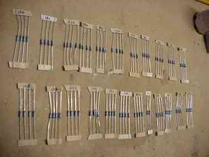 |
The
resistors. Place them in order to be used. I use 0.1% tolerance
however 1% tolerance will do fine (practice). Go for the best...? |
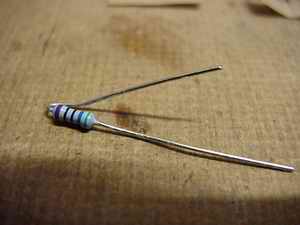 |
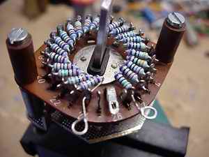
Each
resistor is bent before mounting. One lead a bit higher then
the other. You also can determine each resistor's direction
by keeping the tolerance marking at one side. |
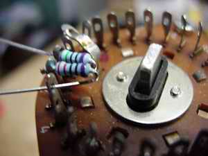 |
The
solderlugs of the switch are turned 45 degrees with a pair of
pliers, so that the eye-lets face outwards. This will ease up
mounting the resistors. I've mounted the resistors at the innerside
of the decks, but it is also possible to mount them on the outside.
As you can see, the return lead is kept under the resistor to
prevent a "short circuit". |
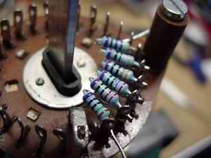 |
The
first resistor is soldered at one lead only, putting the second
in place. Than these are soldered together and so on. The leads
are cut to length when soldered although this is not supposed
to be done after soldering...So cut carefully! |
 |
One
deck ready! Start at step one with zero ohm and increase in
value as you go round. The source is put to step 24, ground
to step 1 and the selector to the amplifying stage. This way,
at step one, the source will "see" full impedance
while creating the maximum attenuation for the amplifying stage. |
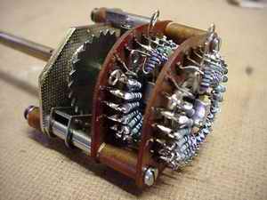 |
Ready!
This way, the switch's dimensions are kept to a minimum and
the tolerance between the two decks will be 0.1% or less!! No
"normal pot" will have such specs!! |
As you may have noticed, I used more common values in stead of the E96 values
as mentioned in the schematic. This really works fine and is done because my
supplier had only these values at 0.1%... Go for the best and stick to the mentioned
values in the schematic!!
Good luck!
_______________