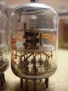
Single Ended headphone amplifier with 5842 triode (1)
29-12-2002
 A new project! Recently I got in hands a powersupplytransformer and supplychoke
by Millerioux. These are old ones, came probably out of equipment of any kind...
I got them from a friend of my, in trade for some capacitors. Both parties happy!
The powertransformer has a relative low secondary highvoltage, not always suitable
for tube-equipment, however, when I saw these, immediately an idea came up.
A while ago, at a fleamarket I bought some small ouputtransformers with 5K primaries
to 4, 8, 16 and 32ohms secondaries. They can handle about 50mA current and are
U-bracket fitted. These in combination with the Millerioux transformers could
make a perfect headphone amplifier with the 5842 as a voltage amplifier.. The
secondaries of the powertransformers are 125, 135 or 145V at 60mA and 6.3V.
The 5842 works fine at a voltage of about 150 to 180V at 25mA each. A good powersupply
can perfectly be made in choosing the right voltage. The 5842 has a mu of 43
and, when calculated, will have an effective amplification of about 3,4 times
when using the 32ohm tap... Normally headphones have a minimum sensitivity of
100dB, so the overall amplification should be sufficient.
A new project! Recently I got in hands a powersupplytransformer and supplychoke
by Millerioux. These are old ones, came probably out of equipment of any kind...
I got them from a friend of my, in trade for some capacitors. Both parties happy!
The powertransformer has a relative low secondary highvoltage, not always suitable
for tube-equipment, however, when I saw these, immediately an idea came up.
A while ago, at a fleamarket I bought some small ouputtransformers with 5K primaries
to 4, 8, 16 and 32ohms secondaries. They can handle about 50mA current and are
U-bracket fitted. These in combination with the Millerioux transformers could
make a perfect headphone amplifier with the 5842 as a voltage amplifier.. The
secondaries of the powertransformers are 125, 135 or 145V at 60mA and 6.3V.
The 5842 works fine at a voltage of about 150 to 180V at 25mA each. A good powersupply
can perfectly be made in choosing the right voltage. The 5842 has a mu of 43
and, when calculated, will have an effective amplification of about 3,4 times
when using the 32ohm tap... Normally headphones have a minimum sensitivity of
100dB, so the overall amplification should be sufficient.
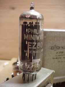 Rectification is done with diodes since the transformer lacks a high voltage
centertap. I added an EZ80 right after the diodes to provide in a "slow
turn-on". There are schematics which use a fullwave rectifying tube in
combination with two diodes as a rectifier but I don't think that's the way
to go: There will always be a different characteristic between diodes and a
rectifying tube, so I chose this option... The electrolytics are from JJ which
I became a couple of weeks ago from AE.
The reviews of these elco's are positive (Angela),
so I decided to give them a try. They sure are a lot cheaper than BlackGate!
There is a double pi-filter, one with a common used choke and one with a resistor
for each channel apart. This way a clean powersupply and good channel separation
is provided for the 5842. The resistor also can be used in fine-tuning the supply
voltage.
Rectification is done with diodes since the transformer lacks a high voltage
centertap. I added an EZ80 right after the diodes to provide in a "slow
turn-on". There are schematics which use a fullwave rectifying tube in
combination with two diodes as a rectifier but I don't think that's the way
to go: There will always be a different characteristic between diodes and a
rectifying tube, so I chose this option... The electrolytics are from JJ which
I became a couple of weeks ago from AE.
The reviews of these elco's are positive (Angela),
so I decided to give them a try. They sure are a lot cheaper than BlackGate!
There is a double pi-filter, one with a common used choke and one with a resistor
for each channel apart. This way a clean powersupply and good channel separation
is provided for the 5842. The resistor also can be used in fine-tuning the supply
voltage.
I have two schematics: First the classical approach. This one
is commonly used, using a kathode bypass capacitor. The second one is also classical
(by WE), but recently "re-discovered". The minus of the last supply
capacitor is connected to the kathode of the 5842. This almost eliminates the
whole powersupply from the signal and the kathode bypass capacitor may be omitted.
An advantage because the bypass capacitor has to be of a minimum of 1000mF to
provide in good bass response but not many good caps are obtainable at this
capacity! The last supply capacitor has to be non-polarised like paper in oils
or MKP's. Also the mF rating of this capacitor is important since you don't
want to have extended bass or a lack in bass... The supply voltage has to be
well filtered before entering this last capacitor because any supply ripply
is put directly on the kathode. So don't simply replace this last capacitor
for the last JJ in the powersupply! I have two GE 50mF/200V paper in oil caps
lying around, so I will build the modern one...
Since I have all the parts, the amplifier will be ready in a few weeks. The "iron" used is easily obtainable at flea markets but, and this is really interesting, since the amplifier runs at relative low current you can do with small transformer cores which makes it interesting to order these from a good transformer maker... Tribute, for instance, is wiling to supply the transformers.. More on that when the amplifier is finished! You can look at the schematics here: "classic" and "modern". At the right I put in a small flash-movie with the components to be used. If the movie is finished (two GE capacitors) click on it and it will run again. If you want to have a closer look at one of the pictures, it will stop on mouse-hover and play again on hover-out...
PS. I have to buy me headphones soon!!!
Ready! The amp is playing and it sounds very good! It has been playing for quite a while now, so the break-in period has passed. I had to make a few changes to the original schematic which is corrected, by the way ( click here to see it). The output transformers are very sensitive in picking up hum, so I had to rebuild the amp for 3 times before that nasty 50hz hum was kept out... This lay-out was the most practible one, however the output transformers had to be shielded with mu-metal to effectively solve the hum problem... If you have to shield for 50hz (powertransformer), always use ferro-metals or mu-metal! Non-ferro metals, like copper, won't do the trick. In the next pages you can see and read about building this amplifier.
Sound quality
This really was a big surprise to me! The amplifier has a most detailed, warm
and very good balanced sound. Voices are well placed (is that possible?), and
there are good dynamics. I have to admit that at first sight, the output transformers
were not that convincing to me... If you see what core materials are used and
how everything is wounded, well, it was not impressive at all. 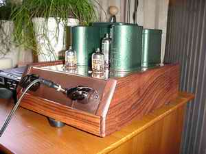 BUT! they do a very good job here! They have been taken from an old single ended
amplifier (I don't know the brand). At the used 18mA they don't have to work,
that's for sure, and that's audible. This adjustment is made through experimenting.
I started out with 150ohms as a kathode resistor and slowly decreased to 60ohms
keeping the B+ steady at app. 145V. At 100ohms and 18mA the 5842 really opens
up, so I kept it that way. I think that this specific working point may be different
for each amplifier and is really worth the effort in finding! You can easiliy
use a pot here to determine this "sweet spot" and replace it afterwards
by a fixed resistor. The second pi-filter has a 1K8 resistor. This resistor
is responsible for a considerable voltage drop, though it is neccesary for good
regulation... The GE paper-in-oil "shorts the signal path". In articles
from Electraprint it is stated that the supply is not audible due to this capacitor;
this is not true! Even a change in diodes, BYV26E for 1N4007, was audible!
BUT! they do a very good job here! They have been taken from an old single ended
amplifier (I don't know the brand). At the used 18mA they don't have to work,
that's for sure, and that's audible. This adjustment is made through experimenting.
I started out with 150ohms as a kathode resistor and slowly decreased to 60ohms
keeping the B+ steady at app. 145V. At 100ohms and 18mA the 5842 really opens
up, so I kept it that way. I think that this specific working point may be different
for each amplifier and is really worth the effort in finding! You can easiliy
use a pot here to determine this "sweet spot" and replace it afterwards
by a fixed resistor. The second pi-filter has a 1K8 resistor. This resistor
is responsible for a considerable voltage drop, though it is neccesary for good
regulation... The GE paper-in-oil "shorts the signal path". In articles
from Electraprint it is stated that the supply is not audible due to this capacitor;
this is not true! Even a change in diodes, BYV26E for 1N4007, was audible!
The JJ-capacitors (available from Angela)
do a good job. They don't sound harsh or bleeched out like most (bad) electrolytics
do. Ofcourse the GE's, which close the powersupply line, do help them! The stepped
attenuator is also responsible for the good sound! It is fun building these
and even more fun using it to upgrade any amplifier! Amazing how good these
stepped attenuators are compared to normal "pots"! Replacing the powersupply
transformer and choke, as well as the output transformer, could be a serious
upgrade too! I know that AE has one available
and Tribute is working on a complete
set for this amp...
A nice amplifier, to say it myself. Interesting because it is made out of (mostly)
flea-market materials. So for little money one can listen to expensive tube
sound!
_______________