A 101D preamplifier with Alexander Naydenov transformers
An evolution of the AD1 preamplifier? Most certainly, it uses the same power supply so both preamps can be swapped to compare without evaluating the power supply as well. Compared to the AD1 variant this design is slightly more revealing and precise in music playback.
The design.
A while ago I wrote an
article covering the basics to build a preamplifier using older triodes or power
triodes without being microphonic or suffering from hum or noise. This design is no other.
That means that an input transformer is used for stepping up the signal and a line out
transformer for stepping down the signal. This seems a bit odd but this is necessary
to keep this preamplifier versatile, meaning to be able to use it for sensitive power
amplifiers as well without being overly noisy. If we don't step up the signal, most of
the amplification will be lost because of the step down at the end. So when next to no
gain is sufficient, a step up input transformer could be omitted. Although I would then
recommend a 1:1 input transformer in stead of a fixed resistor. This because of older
triodes and power triodes do like their grid being connected to ground at a low dcR
resistance.
It must be said that this design is not cheap as well. As it is transformer based, the
sound quality mainly depends on good transformer design. Bad transformers give bad sound.
Good transformers will give good sound but are not cheap. When using good transformers
the triodes' sound will be passed through and can be enjoyed, both older triodes and
power triodes (again, without noise or hum).
Where the previous design was based upon the scarce and insanely priced AD1, this one
is designed using the fascinating
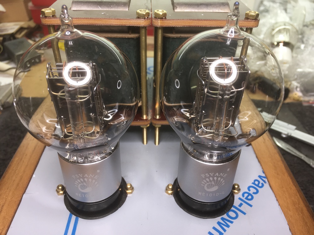
Psvane 101D Western Electric replicas. Earlier tests, together with a friend,
learned that these come very close to the original tennisball versions by Western
Electric. And, also very important, they look very good although that is subjective..
Transformer choice.
As said, good transformers determine sound quality, so choice is very important here.
We need an input transformer, a line output transformer and an autoformer. Like in the
AD1 version a Tamura TD-2 input transformer is used. It is rated 600 Ohms to 10 KiloOhms
which is essential a 1:4 ratio. It is capable of handling line level signals and is
of undisputed quality. A good and affordable alternative could be the Lundahl LL1538XL
which can be connected for both 1:2.5 and 1:5 step up ratio at line level.
As attenuator an autoformer by Tribute
is used. Together with Dave Slagle
these are the best money can buy at the moment. Both are capable of handling 8V RMS
at 20 Hz, according to datasheets, which is more than sufficient as output device in
this design. In this case the choice for Tribute was mainly determined
by used core material, nano-crystalline, which in the end matched the line out
transformers core material. So for an undisputed quality line out transformer I contacted
Alexander Naydenov and
asked him to make me a pair suitable for loading the 101D and stepping down with a 5:1
ratio. Maybe interesting to read what he said to me about transformer design:
In this version of transformers I've applied my current peaking of knowledge and research
together with the best kind of materials. Nanocrystalline core material, famous for the
revealing of micro information together with energy and holographic preciseness and
windings made of OCC copper wire which gives specific calmness, holographic spaciousness
and sense of musical flow. Finally with paper dielectric material and vibrational tuning
using tonewoods, the end result is a unique achievement.
The interleaving is optimized for universality, the transformer is suitable for tubes
with Rp between 1k and 6k. I've also employed the usage of a special innovative winding
which reduces coil to coil tertiary leakage inductance in double bobbin constructions.
This gives a smoother high frequency response.
A few words on distortion and transformer resonances:
In preamps, distortion should be kept as low as possible. At low frequencies it is
formed by the decreasing load value due to limited inductance. In technical literature
an elliptical loadline is described. At high frequencies the main distortion increasing
factor is shunt capacitance, which decreases the load value similar to the way primary
inductance does for low frequencies. Distortion increases with frequency response
roll-off and phase shift.
Resonances can be neglected if they occur way above the audio band, 40kHz and above and
are low in Q. Even a 30kHz resonance can be neglected if it's dampened enough, thus
not contributing to frequency response, phase shift and distortion. In fact, every
transformer has a self resonance in the audio band, but in practice (together with
a load and a low driving impedance) it isn't visible.
A high Q resonance though, when close to the audio band can give problems. High leakage
inductance transformers should have their secondary optimally loaded to reduce the Q
and give a smooth roll-off. The worse resonances are dips that result from a Ls to Cs
resonance and they get bad with loading. Ls to Cp resonances are easier to tame.
In the end, my opinion is that the specific sound of an audio transformer comes mainly
from the materials used and the way they're combined by the constructor. Care and
preciseness in building is needed as well. Little comes from measurements, but I'm
keeping them to the highest standard possible anyway.
Power supply.
The AD1 power supply will be used here as well. The 101D filament voltage and current
are alike the AD1 and thus can be drawn from the same raw supply. High voltage,
which is around 280 Volts, has to be brought down as max operating voltage by the
101D is 190 Volts. The earlier test also revealed that the 101D performs really well
from 180 to 160 Volts. To realise this a 150 Volt voltage regulating tube is used. First
tests showed that the 0D3 performed well but an European variant was chosen: the 150C1.
Why? I like the orange glow better. Later on the 150C1 was changed into the Pressler
GR150DA which a real joy to look at with its mesh anode and cathode. Sound differences
are minimal, so purely a choice base on aesthetics. As the RGN1404 rectifiers will
provide the high voltage before the Coleman regulators get the 101D going, the VR-tube
will be lit before the 101D draws current. As the 101D becomes operational, it will suck
the needed current from the VR-tubes' flow and will be biased by the total current
flow. Doing so a cathode capacitor can be omitted as the bias resistor value can be kept
low as well.
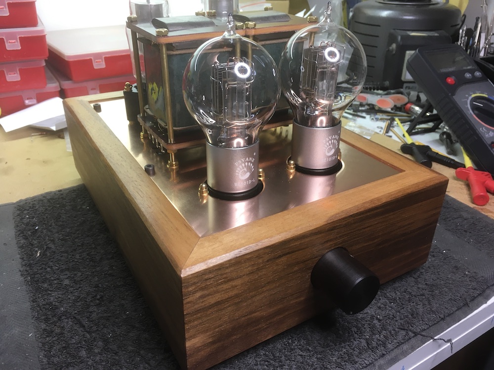
Building it.
The same style in chassis is chosen as the power supply and the AD1 version: an American walnut
chassis with copper top plate measuring around 20cm x 30cm. Lay out of components is
mainly determined by shortest electrical connections. In this case the VR-tubes are
placed at the back side, the line output transformers in front of these and the 101D
triodes up at front with the line input transformers mounted directly beneath them.
The rather big autoformer is mounted under beneath the line output transformers. This
way the longest wire for signal is that one from (source) input to input transformer, or
from back to front of the the chassis. Of course this is peanuts compared to the meters
of copper windings used in all the transformers..
How does this design sound?
It has a different character compared to the AD1. Where the AD1 can be mesmerising on
voices and violins and alike, the 101D excels in transparency and energy. It is more
holographical yet not analytical. Probably the omitted cathode capacitor adds to this
as well. There is no noise coming from the VR-tube, in case you are wondering.
And for looks?
Well, totally different. The 101D version lights up like a christmas tree and has an
open electrode structure in which the filament glowing can be seen. Whereas the AD1 shows
nothing, not even the tiniest glimpse of a filament. Again subjective.
Building progress in photos.
A bunch of photos just to show how the preamplifier is put together. Enjoy!
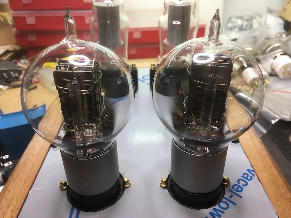
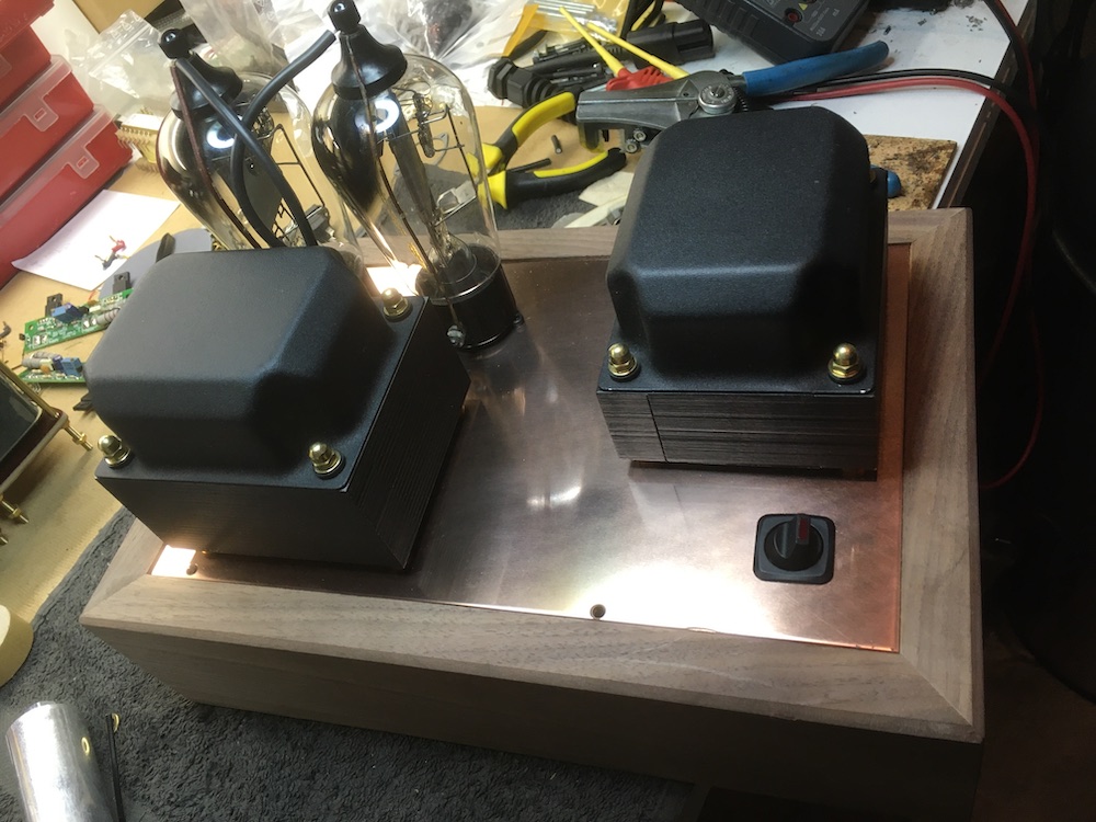
Alignment of the 101D with in the background the VR-tubes visible. And yes, this is
not the 101D but the 205D.
Liny out transformers te be placed in between..
..and mounted. All components on top are ready te be interconnected.
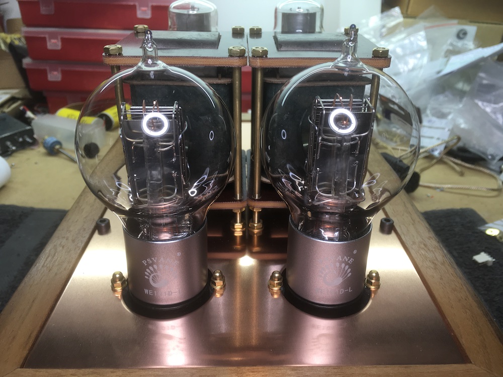
Shot up front showing the copper top plate. The copper is not treated nor varnished.
Simply not touch it and it will age beautifully.
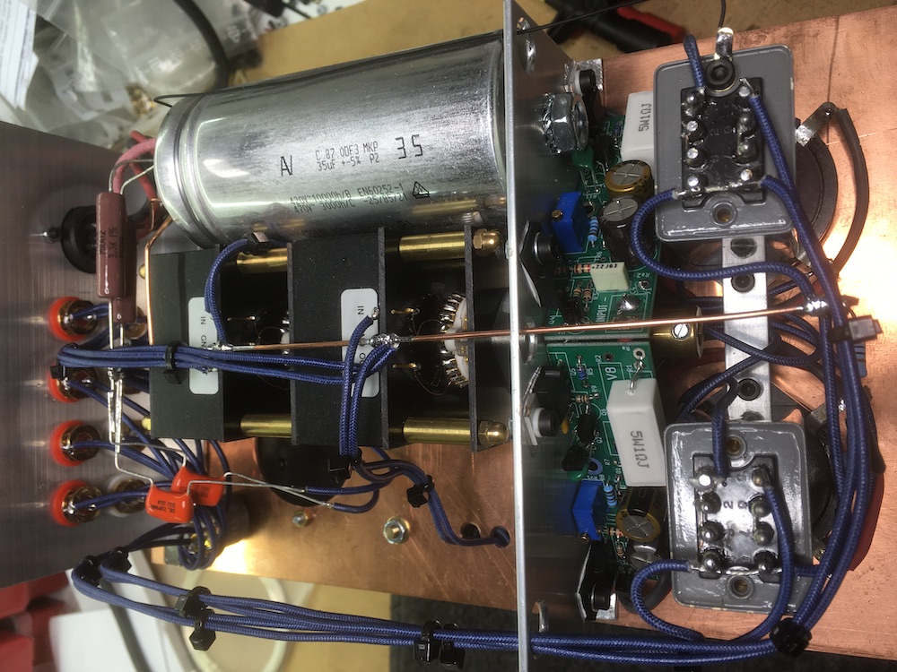
Underside with at the right side the input transformers mounted hanging to the sockets.
Coleman regulators are mounted on the same piece of aluminium on which the autoformer
is mounted as well. This aluminium strip is mounted to the copper top plate using the
threaded rods of the line out transformers. Top left the last power supply capacitor.
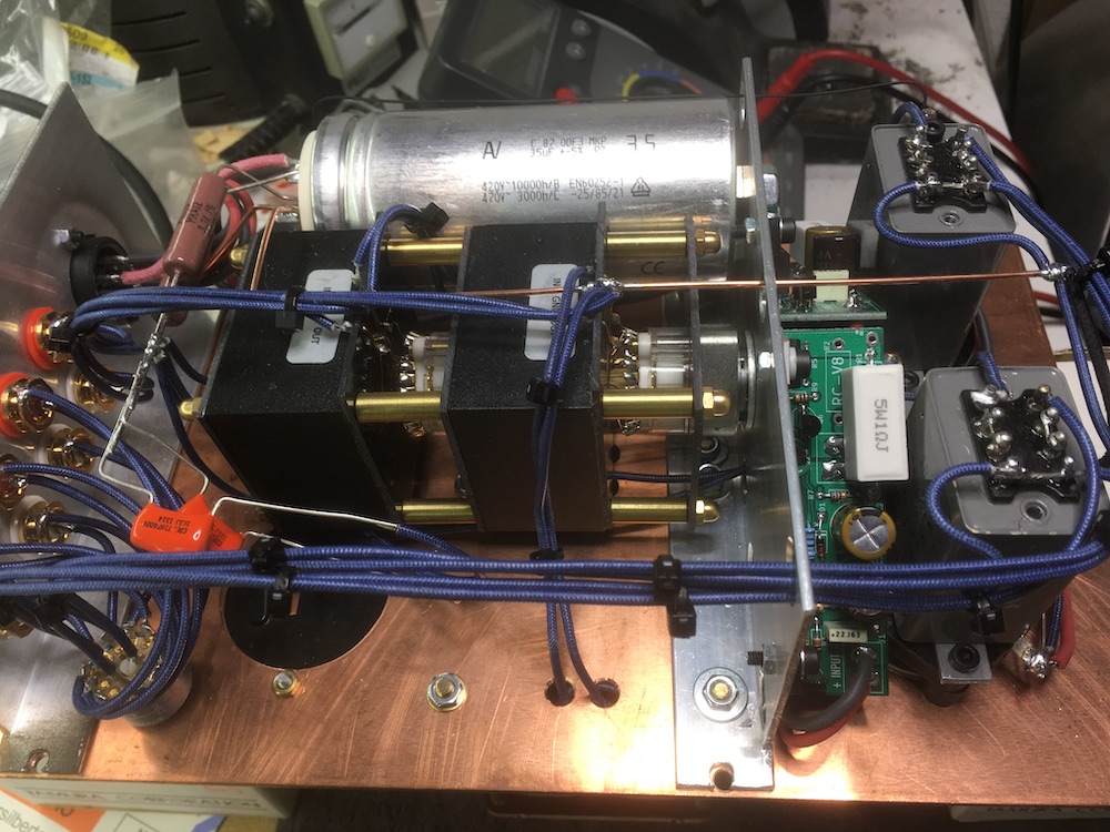
Shot from the other side showing the orange drops as bypass caps for the VR-tubes. Also
the smallish Elma input selector switch can be seen.
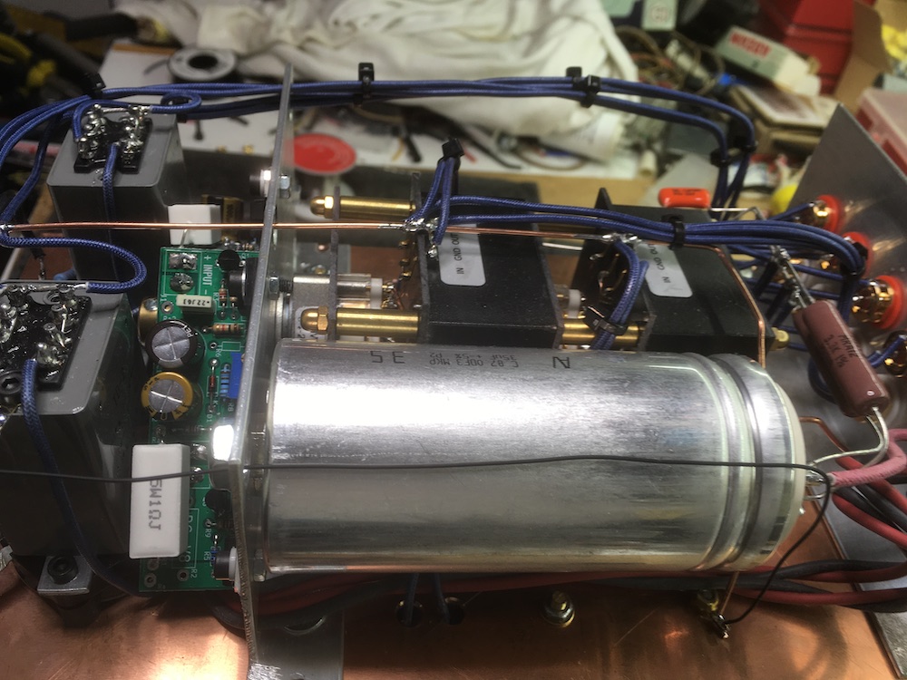
Again but from another angle showing the ground connection to the input transformers.
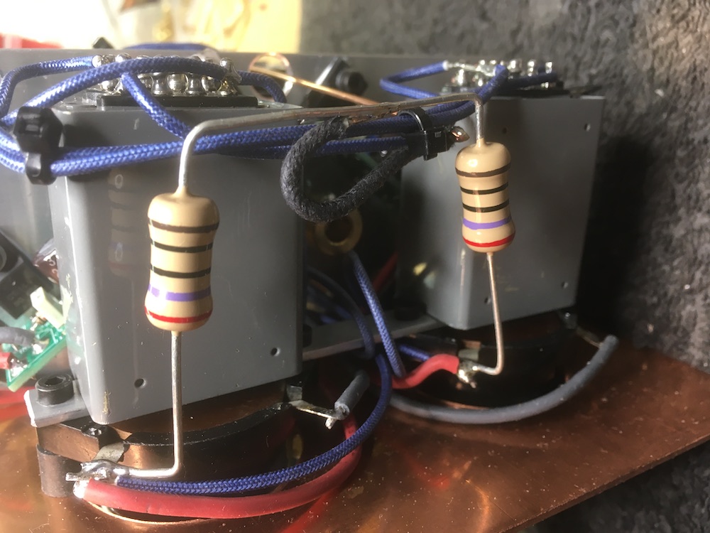
The bias resistor for the 101D's and VR-tubes, a two Watt AudioNote tantalum resistor.
Both UX4 sockets for the 101D and the input transformers are mounted using M3 rubber
standoffs.
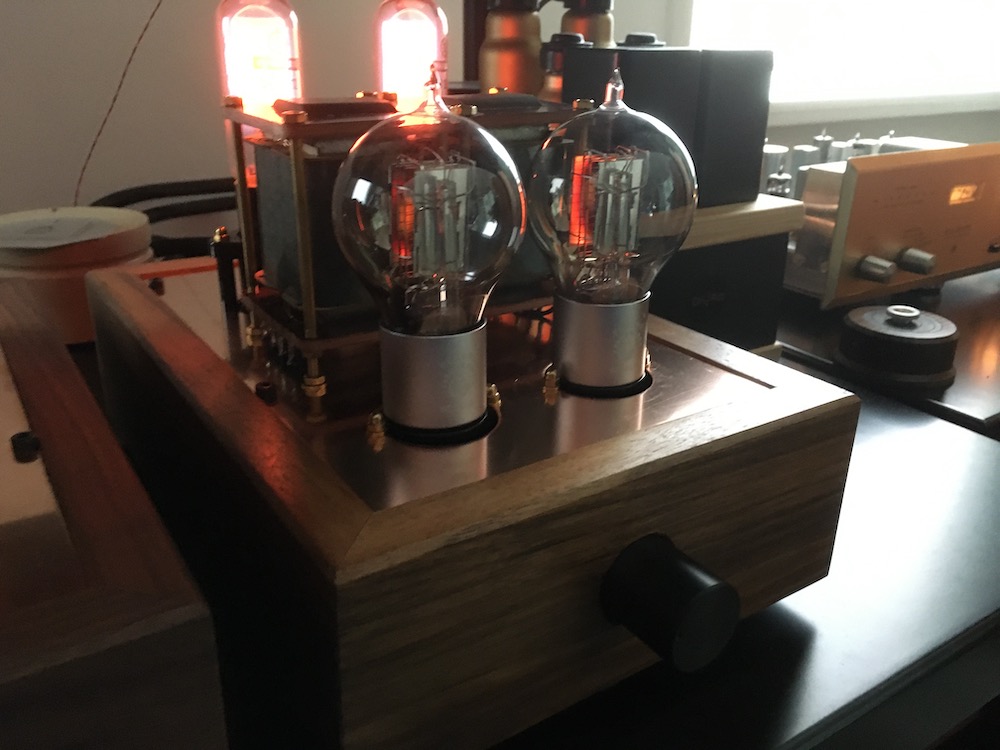
The preamplifier in use..
Another picture to show the GR150DA which has an enchanting glow. In here the R86 was used
as one of the 101D had to be replaced because of a cosmetic defect. The R86 is a French
equivalent to the 101D apart from the socket type: B4 versus UX4. I prefer the 101D's
sound though..
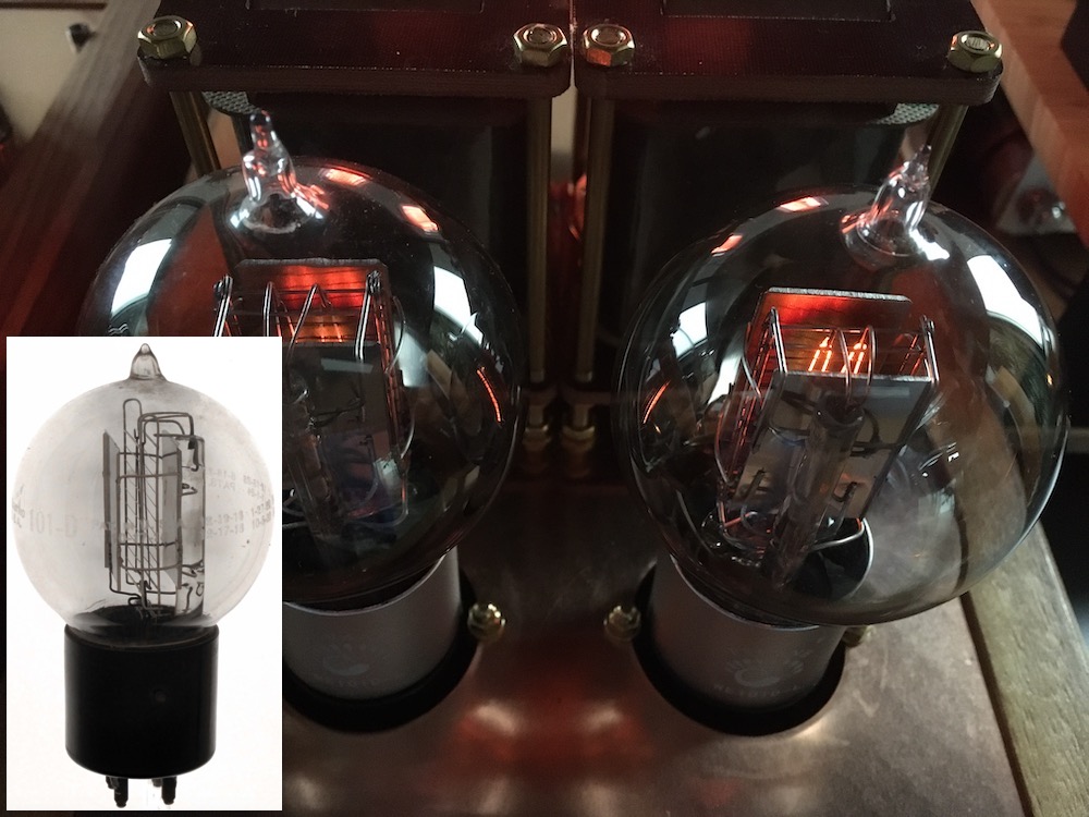
The 101D's open electrode structure showing filaments glowing. Take notice of the glass
supporting rods inside the glass. Just like the original Western Electric tennis balls
inserted left (Photo borrowed from the net).
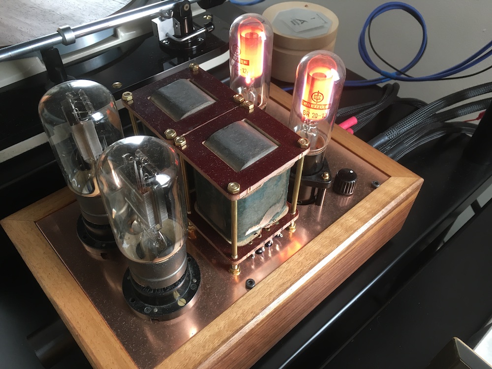
And this is the power supply, also used for the AD1 version. A couple of RGN1404 followed
bij a C-L-C filter and under the bonnet the raw DC-supply for the 101D's filament.
The diagrams.
Remember this is a two-box design where the power supply is in a separate box from the
preamplifier. An umbilical cord with six connections is used to interconnect them. The
last supply capacitor is included in the preamplifier box with the dropping resistors.
The raw DC-voltage circuit needed for the Coleman regulators, is in the power supply
box as well. This way no AC-voltages are present in the preamplifier box.
Diagram when using 150C1 or 0D3 as VR-tube

Diagram when using the more obscure GR150DA VR-tube. Notice the 1M extra resistor needed
for ignition.
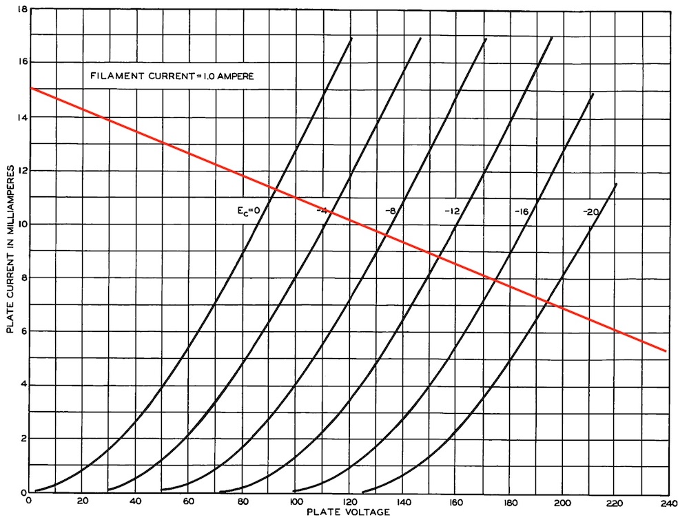
This is the chosen operating point.