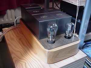
Single Ended power amplifier with type '45 triode (5)
Power "on"?
The actual secondary transformer voltages are well within 10%, thus within factory
standards for filament specifications. Nice! No transformer "suffers"
from mechanical hum and temperature is well below 40° C. A 2.5 Ampere slow-blow
fuse does the trick for both powersupply tansformer and filament transformers
as inrush-voltages are not that huge.
Measurements...
 The
amplifier has good measurements: Less than 0.2mV on the loudspeaker terminals!
This results in a very quiet amplifier even on my 101dB system... Further on
the overall frequency characteristic of the OPT (and interstage) is: 19Hz up
to 65Khz at -1dB at "full power". This "full power" is 2500
milliWatts(!), almost one quarter more than possible according RCA specifications
when using the 245... Input sensitivity is around 9 Volts (Ac) for full output.
The
amplifier has good measurements: Less than 0.2mV on the loudspeaker terminals!
This results in a very quiet amplifier even on my 101dB system... Further on
the overall frequency characteristic of the OPT (and interstage) is: 19Hz up
to 65Khz at -1dB at "full power". This "full power" is 2500
milliWatts(!), almost one quarter more than possible according RCA specifications
when using the 245... Input sensitivity is around 9 Volts (Ac) for full output.
The amplifier will be evaluated listening to :
- ST 45 - RCA
- UX245/345 - RCA/Cunningham
- 45/n mesh - Sophia Electric
- VV45 - Vaic
- 2A3 - JJ-electronics (adjustment of cathoderesistor!)
- 2A3/n mesh - Full Music
Let the music play....
As mentioned in Super E-cap, these BlackGate NH in Super E-cap take a really
long time to break-in.. For about 2 weeks the sound character will change from
"good" to "bad", no joke... These tine caps take a long
time to break in. My expectations are high: if practice complies with my theory
I'll be happy! In other words, I'll get back to this...
Adjustments.
 The hum pots are bypassed with resistors to keep out an eventual negative influence.
Fine adjustment can be done in several ways: see the schematics: Figure A represents
the "original" situation without extra resistors. Figure B has parallell
resistors and thus the total resistance of the hum pot will decrease and draw
more current together with the filament. This means that the adjustment is somewhat
rough: you can easily pass the point where the tube is silent. This can be problematic
with unbalanced filaments. In figure C series resistors are added. This means
that the total resistance of the hum pot will increase thus drawing less current.
However the effective area for fine adjustment will be smaller. This means that
a possible unbalance must be known prior to determining the value of the extra
resistors. When dimensioned correctly fine adjustment will be more accurate.
In short: Determine by using figure A a possible unbalance, calculate the values
for the resistors in figure B (not too low - more current!) and when applied
without effective lowering residual hum, go to figure C.
The hum pots are bypassed with resistors to keep out an eventual negative influence.
Fine adjustment can be done in several ways: see the schematics: Figure A represents
the "original" situation without extra resistors. Figure B has parallell
resistors and thus the total resistance of the hum pot will decrease and draw
more current together with the filament. This means that the adjustment is somewhat
rough: you can easily pass the point where the tube is silent. This can be problematic
with unbalanced filaments. In figure C series resistors are added. This means
that the total resistance of the hum pot will increase thus drawing less current.
However the effective area for fine adjustment will be smaller. This means that
a possible unbalance must be known prior to determining the value of the extra
resistors. When dimensioned correctly fine adjustment will be more accurate.
In short: Determine by using figure A a possible unbalance, calculate the values
for the resistors in figure B (not too low - more current!) and when applied
without effective lowering residual hum, go to figure C.
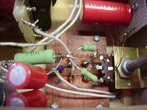
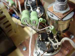
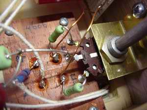
The following pictures show figure B, the actual situation in the ampliefiers, and under beneath figure C.
_______________