MM RIAA correction amplifier, the quest
See here for the completed design and built..
Notice! Filament connections are pin 4 and 5, not 5 and 6 as in the diagrams!
March 06, 2016
I stand corrected. The CCS load combined with dc-coupling makes it virtually impossible for the 6S4A to settle. Plate voltage is unstable and
in almost all the cases ends up at max available voltage leaving no headroom for amplification. This is not a stable circuit, thus a bad design.
The CCS has to be replaced by either a plate resistor or a plate choke for the circuit to become stable. A plate resistor has to have a minimum value
of about 12K to suit the plate impedance. Using 10K at 16mA requires 160 Volts which is about 85Volts short. Lowering plate current will increase
plate resistance so that is not a suitable solution as well. Using a plate choke will do but requires a bigger chassis and attention to strayfields. One
of the design objectives was keeping it compact and this will not do.
Stepping up to the parafeed design. The D3A in triode allows for lower plate voltage and has lower plate resistance. When the input stage is slightly
modified, plate voltage drops to about 100Volts. Settling the D3A for 13mA at a plate voltage of 120Volts, allows for a 7K7 plate resistor which is
sufficient for linear loading. Amplification is sufficient as well to feed into the step down parafeed transformer without loosing line level output.

February 28, 2016
As always Acoustic-Dimension delivered the goods very quickly, so the 50μF
could be mounted to implement the Tentlabs MEC-50. Building compact always means being creative with space as the design changes, especially when
being so confident not building a testrig first.. So an AN capacitor was needed to fit the small space left together with the MEC-50. As you can see
on the picture this is about hardwire-hell, so I encourage anyone not to build like this..
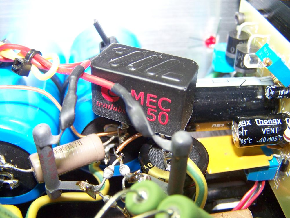
The MEC-50 works like a charm. Huge ripple reduction at the cost of almost no space and a voltage drop of only 5 Volts. It is mechanically silent
and has no strayfield, all good. The ripple reduction results in a clean DC being fed to the fet and allows for omission of the capacitor right after the fet
with no residual hum. Getting rid of this electrolytic is audible as well. Less strain and more ease, that being put a bit exaggerated to
point out what I hear. The design and soundquality just got better at the expense of about 35 €.
Next step will be replacing the 6S4A by a triode connected D3A and using the Magnequest B7-10K parafeed as line-out transformer..
February 26, 2016
Well, subjectively speaking the amplifier performs really good. Full bodied and detailed sound. I guess that some components could be tweaked, but it
is fine as it is using Kiwame resistors, AN and BC electrolytics and cheap MKP caps in the power supply. Coupling cap is Kemet, a paper in oil
cap from the old days. Maybe a Jupiter or Duelund coupling cap will spice things up? (not only financially). To my surprise the Orangedrop caps in the
RIAA-filter sound very much okay! Love it.
What can be optimised is the power supply. Although the capacitor multiplier works fine, a pi-filter before the fet is necessary to keep out hum without
having to use a big C right after the fet. No phase shift will occur within the audio band when leaving this one out. So we need a good pi-filter before the
680μF. Here comes the MEC-50 to the rescue. This is an electronic choke made by Tentlabs and Vanderveen. It provides 60dB ripple reduction at a maximum of 12 Volts voltage drop.
..and it is small, very small!.
Only thing is that the first cap has to have a minimum capacity of 27μF. When the ordered 50μF capacitor arrives, the pi-filter goes in and the
capacitor right after the fet goes out. Things will then look like this:
February 22, 2016
All the parts are in and after determining component placement the chassis has been prepped by drilling the appropriate holes. The subchassis is
prepared as well and can also support the line-out transformers for version (2). As planned before the powersupply is at the front in the chassis
and the signal section in the back close to the RCA-input and output connectors. The regulators are mounted on the heatsinks, the power supply capacitors
directly to the chassis. Power transformer is placed on top using a rubber damper. The subchassis is also isolated from the chassis using rubber dampers.
Components are soldered directly to the subchassis for signal ground. I used a regulated supply board in stead of the 78S05 regulator, came through eBay
costing a whopping 5 dollars including shipping costs..
Some thoughts..
- The used toroid power transformer has a relative high voltage of 310 Volts AC which results in almost 430Volts DC high voltage. While this allows for some headroom for the used CCS's, one could get similar results with a lower high voltage winding of about 280 Volts AC. This will result in dissipating less by the IRF840 fet. A CCS needs some voltage drop to be able to swing the triodes' amplified voltage. In version (1) this is about 2 Volts RMS, so a theoretical voltage drop of about 10 Volts would be enough. I chose a voltage drop of about 50 Volts, surely enough for version (2) as well..
- The adjustment of both the 6S4A's is critical since it is directly coupled to the plate-voltage of the E80F. Despite the CCS which sets for a maximum current, the 6S4A will follow the E80F. This is not a real problem as long as the 6S4A cthode voltage is kept about 5 Volts higher than its grid which resembles the E80F plate voltage. So slightly different settings may occur if the E80F's are not matched.. Also keep in mind that some headroom is needed for the CCS, so adjust for about 260-280 Volts on the 6S4A plate.
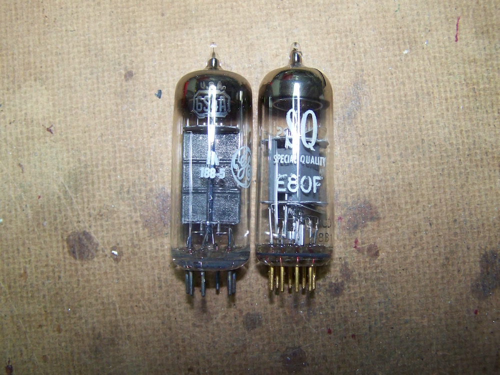
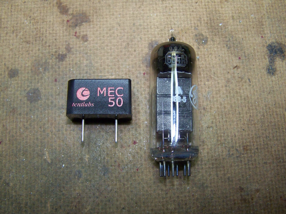
E80F and 6S4A..
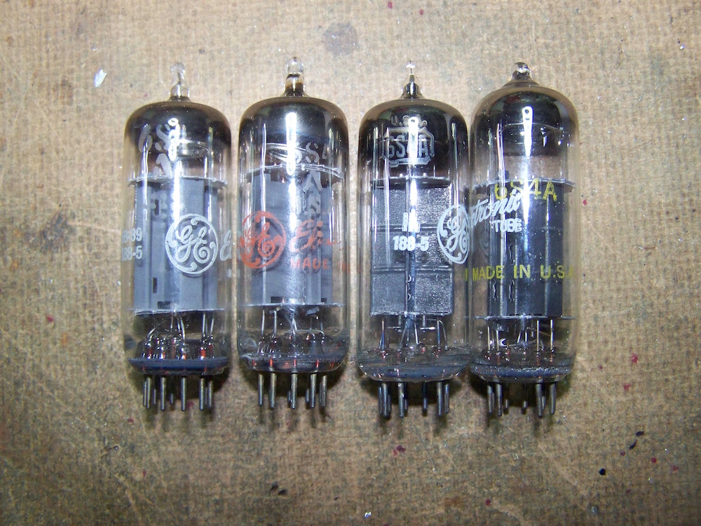
Different types 6S4 and 6S4A.
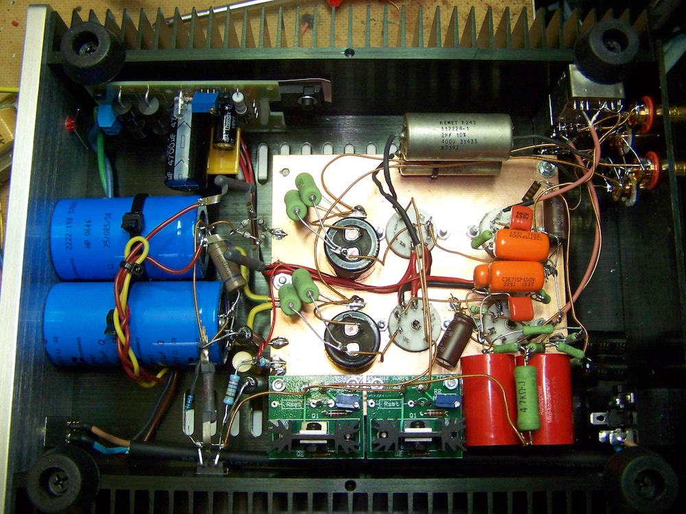
Photo showing the first build..
February 20, 2016
So it all began with the publication of Sasa Cokics phono amplifier on 6Moons. Cloning his design led to improvement (as subjective as that may sound) and now a redesign with the use of less expensive tubes and a variation using a parafeed transformer for low output impedance. RIAA correction is still part of the input pentodes' plate load being dc-coupled to the next stage. Power supply is FET-regulated which allows for a compact built.
Input stage.
I am sticking to the E80F here. Less noisy than a EF86 and available in Special Quality (SQ) for use of >10000 hours. Not really cheap but it is the most
important stage in this design. It is pentode connected to allow for desired amplification. The RIAA-correction circuit is incorporated in the plate load
using good available component values. Deviation from the RIAA-curve is within .5dB. In this design I will use a mix of Orange Drop polypropylene and polyester
capacitors which were matched to needed values. They are inexpensive and have good reputation. Ofcourse Silver Mica would be more audiophile but also be
costly. Soundquality is more design- than component choice dependent anyway. Further more Kiwame resistors are planned. A cathode resistor and capacitor
bias the E80F. I like the Elna Silmics for their sonics but it might be possible to use an inexpensive red led and infrared led (950nm) in series to get the
needed bias voltage as well, although I am not so confident doing this at only 1.3mA plate current. The plate voltage is about 120Volts with a slightly lower
Vg2 and using 75K plate resistor results in sufficient gain compensatng for the 20dB loss in RIAA-correction.
Second stage (1).
DC-coupled so operating at a higher cathode voltage than normal. To leave some headroom for voltage gain, a voltage drop of no more than 150V over the tube is
required. That narrows down choice a bit. Power supply voltage of 315 Volts allows for enough voltagedrop over the CCS for proper amplification. Voltage at the
cathode is &plusm;120 Volts, so the filament supply has to be lifted to be safe. Looking at the improved design a double triode is used, an E182CC or 5687,
allowing one tube for both channels. This design uses four tubes, 2 for each channel, for optimal channel separation. Personally I do not think channel
separation is a real issue when using one double triode for both channels since cartridge channel separation is often worse. To allow for some choice in triodes
a CCS (constant current source) is used. CCS allow for higher Rp triodes at the expensive of higher output impedance. When proper interlinks are used up till
one meter length, one should not have any issues on regular following equipment. When longer interlinks are to be used as is not so regular equipment, see
next paragraph (2). A very good sounding tube is the 6S4A, designed for television applications. Affordable as well! Cathode to heater insulation is not that good
meaning AC-heating can not be used in this application. Choosing an operating point that fits the design resulted in the same cathode resistor value as used
with the E182CC or 5687. Output is capacitor coupled and kept at 2μF to allow for acceptable roll-off with a 10KΩ next stage input impedance. If a
100KΩ input impedance is present, a 0.47μF would be sufficient. The cathode decouplng capicitor can be kept as low in value as 22μF, it has to
have a minimum voltage rating of 160 Volts. A nice candidate would be the Audio Note Kaisei (small) or maybe some film type like Auricap (BIG).
Output impedance is approximately 4KΩ.
Second stage (2).
Still DC-coupled but with a step-down transformer output. To keep the overall gain acceptable, we now need more amplification on this stage. The D3A
triode connected and CCS loaded has an amplification factor of 77 and can be used with 150 Volts over the tube at 20mA. Lowering the cathode resistor to 6KΩ
matches the E80F. Coupling the D3A with a 0.47μF to a Magnequest parafeed B7-10K (or B7-15K) steps down the output voltage to line level. The higher
impedance of the CCS allows for a smaller value coupling capacitor than mentioned at (1). The B7-10K has a secondary of 500Ω with a center tap, so a balanced
connection to the following equipment can be used as well. And the B7-series is small enough to fit most cabinets, just keep it away from the power transformer.
Output impedance is approximately 500Ω.
Power supply.
To keep things compact a capacitor multiplier is planned. The voltage takes about a minute to reach the end voltage which allows for the tubes to heat properly.
Capacitors are made by BC, heavy weight and fine quality. The 1000μF is responsible for the slow rising voltage, the zener-diode string references the final
voltage. As the power supply is slowly rising the four tubes are heated well before high voltage hits their plates. No extra channel separation is necessary
between the two CCS's since its power supply rejection ratio is sufficient. The IRF840 must be cooled properly using a heatsink.
The heater supply consists of a valtage stabiliser which has to be cooled properly, especially when using the 6S4A's! Also it needs an elevated voltage
to stay within the maximum allowable heater to cathode valtage of the second stage. Around 75 Volts will do the job.
The chassis.
A small aluminium chassis with integrated heatsinks was ordered through eBay. The heatsinks have sufficient cooling for the IRF840 and 78S05. The toroid power
transformer will be put in front on top to allow placement of the signal section as close as possible to the input and output RCA jacks on the back. The four tubes
are planned on a subchassis which will be decoupled from the chassis by rubber dampers, as will be the power transformer. The subchassis will be a copper plated PCB
which will be used as a ground plane. This ground plane serves as signal ground meaning that all components connected to signal ground can be directly soldered on
the PCB without using a star-ground scheme. I have been using this method succesfully in both RIAA-correction- and preamplifers. It is not "better nor
worse souding", just convenient.
Waiting for the parts, so to be continued..