A RIAA-amplifier design with odd tubes
A RIAA-amplifier with the pentode CF50 and triode AC2..
For some time now I have a RIAA-correction amplifier in use which holds some odd tubes (or valves). Reason for building this one
was curiosity about the first microphone pentode ever developed by Philips. The here presented design has
been developed to my preference in tone and character which is a direct reference to what I hear and experience when listening
to (mainly) classical music in concert halls. I deliberately use the word experience, as listening to music is about the experience
where the ears and eyes receive but all your senses together will tell you if emotion kicks in. Only when that happens, music becomes
emotion and is subjective, different from person to person. I have yet to see measuring equipment which can predict that. It also
means that you may not like the sound of this correction amplifier at all as it reflects my personal preference.
Philips CF50.
This is the first pentode developed for microphone use. Reading the datasheet made me very curious for using it as the first stage
for a RIAA-correction amplifier as a microphone is about the same as a cartridge signalwize. Design goals set by Philips must have
been impressive looking at the datasheet:
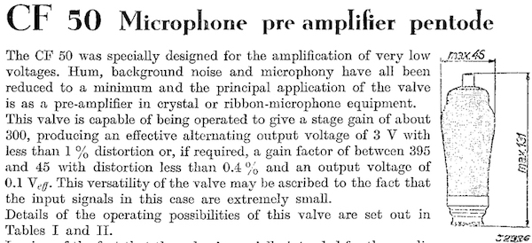
The CF50 has a topcap but it supports the grid and not the anode (plate) as often seen. I have heard some people say that this is very
inconvenient but most probably was a result of the design goals as the tiny signal now is kept clear of all influences of other
connections at the base. This however introduces an other challenge which is keeping the tiny signal free of hum bringing it all
the way up to the top which is about 13cm. So not only the wire has to be shielded but the topcap as well. If you don't do this,
hum will be the result. So using the readily available ceramic topcaps on the marketplaces now-a-days will not work. You will
have to search for old stuff, as these were frequently used in older (radio)equipment where grid connections on topcaps were
commonly in use. If you can't find these shielded topcaps or make your own, this design will become a "humplifier"..
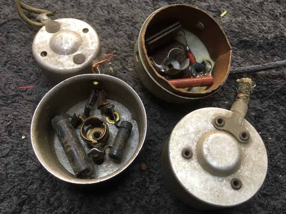
Some examples of shielded topcaps with isolated contacts for the grid.
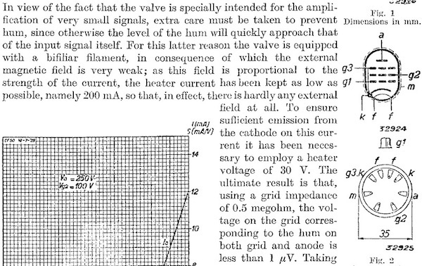
Another challenge is the (seemingly) excessive heater voltage for the CF50: a whopping 30Volts at 200mA. That is 6Watt for the
heater, compare that to the 1.9Watt of an EF86. This was primarily done to keep the current low as possible at that time and thus
stray fields as well. You can read about it in the datasheet as well:
For me this is interesting. More power on the cathode is one of the things I always liked, soudwize. No, not really "green",
I know.. Size does matter, as some say, and the CF50 is as big as a powertube. As well as cathode power I always liked bigger
glass envelopes on tubes as they do not get as hot as the more moderns ones, which has an audible effect as well. Anyways, those
were some of the aspects that got my interest and of course the fact that no one seems to be using it, or at least, is writing
about it. So here we go.
Correction filter.
As we all know, the signal coming from vinyl is modified by decreasing the lower frequencies and exaggerating the higher frequencies
for the cartridge to be able to mechanically track these. So the RIAA-filter has to correct this back to the original signal.
In this design the filter is part of the anode (plate) resistor which value determines the amplification factor of the pentode.
In effect, a RIAA-filter dampens the total signal about 20dB in which it amplifies the lower frequencies and weakens the higher
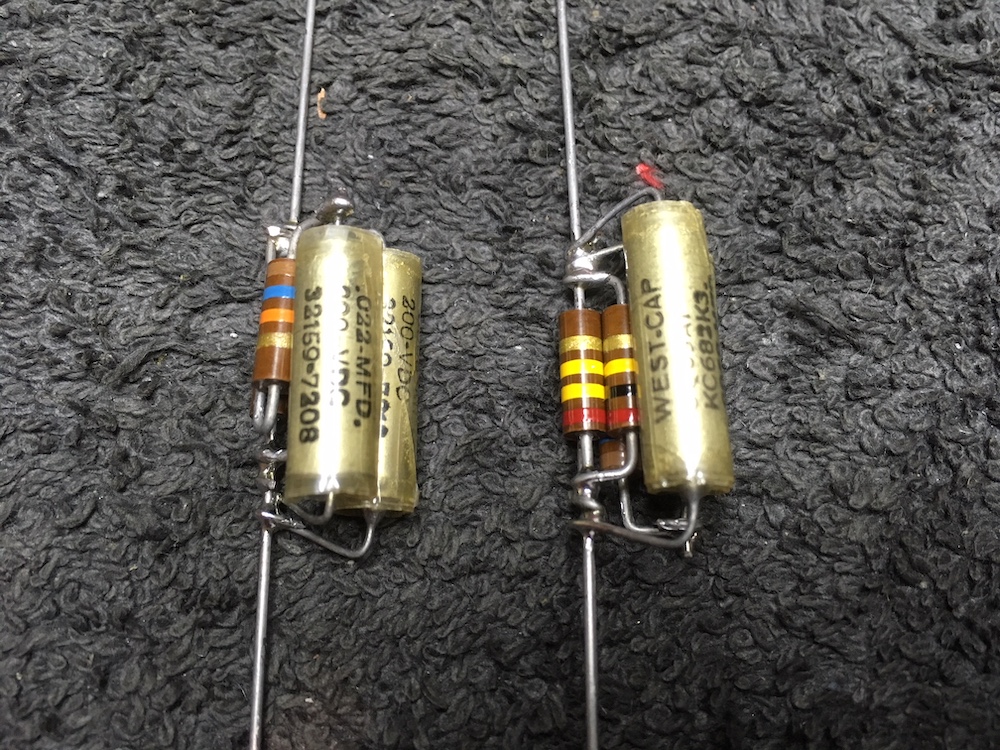
frequencies. This is done using two poles (500Hz and 2122Hz) and thus has two resistor/capacitor combinations. Beside their value
is very critical, these have a significant impact on sound as well: It does matter which type (brand) capacitor and resistor you choose.
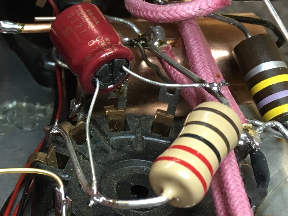
To me a combination of Allen Bradley (AB) carbon composition resistors and (New) Old Stock paper-in-oil capacitors translate to magic.
The hardest thing however, is to get the exact values in these as AB most of the time are far off their original values and (N)OS
paper-in-oil capacitors are seldom seen in the needed values and often are far off their values as well. A sort of quest was needed
for me to get all of them, selected for correct value and matched for both channels as well. Many might be worried about noise coming
from carbon composition resistors in this application, but I experienced no audible noise here.
With special thanks to Acoustic Dimension and Audiomagic!
CF50 Cathode resistor and decoupling capacitor.
These have also a direct affect on sound. I like the combination of Audio Note non-inductive tantalum and Elna Cerafine or Silmic II.
It is what I used for the CF50 cathode. For audible reasons I prefer the 2 Watt over the 1 Watt AN tantalum, although the power rating
is way above what is needed. The tantalum has a directness and pulse that is awesome and the Cerafine somewhat softens the tantalums
sibilance. Perfect combination. Definitely not cheap but imho worth the investment for sound. For operating point I used the table
as shown in the CF50 datasheet. 100K Anode resistor at 200Volts supply and a 2K2 cathode resistor for 0.7mA anode current. I deviated
a bit by using a 110K anode resistor as part of the RIAA-filter, but it all works out just fine.
The CF50 G1 configuration and step-up transformer.
Normally a 47K resistor would go here. As I fancy MC-cartridges I do not need 47K here. I like to have a very low grid resistor and how
much lower can you go than using the secondary of the step-up transformer? It has to be part of the topology when doing that, meaning
that it has to be mounted near by the CF50 on the same chassis. No longer I can use MC step-up transformers in a separate chassis
but what I get is rewarding. So be sure about the step-up choice as it will be part of the RIAA-amplifier itself. Of course a switch
could be introduced for source selection. My favorite up until now is a Tamura MC-T which matches beautiful with my SPU Meister Silver
and the Koetsu Rosewood (on loan at the moment).
The CF50 G2 power supply.
This one is easy. Since the CF50 will be direct coupled to the next stage, and G1 of that stage is biased at -3 Volts, we can take
the cathode voltage of that stage for the G2*. I will be slightly higher than the anode voltage but fits well within the CF50
specifications. This way the supplied voltage is sort of stabilised and anode and G2 will fluctuate together with operations of the next
stage. A happy marriage..
CF50 heater supply.
A toroid transformer with two 12Volt secondaries in series supplies for a 30Volt DC heater voltage. Nothing fancy, just a bridge and
a C-R-C filter has been used, referenced to ground.
Next stage..
I thought it would be nice to use a triode from the same era for the next stage. A triode with medium to high gain, suitable for
transformer coupling and with European sidepin base. Since I had a Tamura A-875 at hand wich, as I can recall, has been developed
for a single 6SN7 stage, I decided to go for the AC2. Although this might be a close call as the AC2 Rp is 11K and the rating of
the A-875 is 17K.. In many older applications however, the AC2 is transformer coupled as well, so it might be that it will be happy
with 1.5 times Rp loading. Drawing a loadline confirms this: An anode resistor of 17K at 165Volts idles at 0Volts at almost 10mA. Drawing
the loadline results in enough amplification as the datasheet lists. As the transformer has some headroom (over 100He static induction)
the actual load bij the A-875 probably is somewhat higher than 17K..
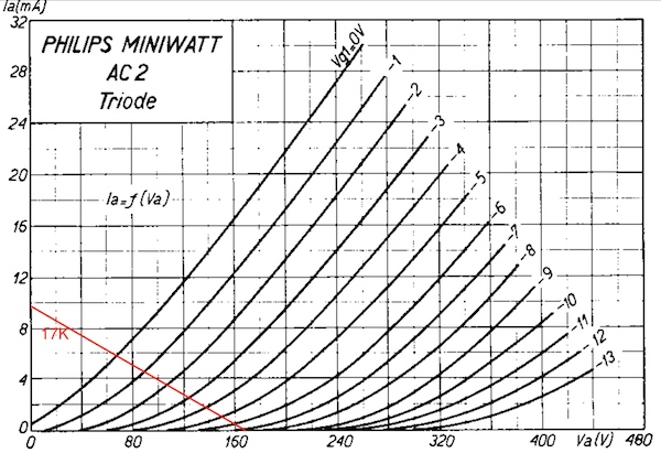
AC2 loadline for 17K anode resistor and anode voltage change.
Maximum resistance between heater and cathode is defined as 20K, so cathode resistor value is set at 20K as well with the heater voltage
lifted to 130Volts to address the allowed 50V voltage difference between heater and cathode. This results in 6mA current flow through
the AC2 which is well within specs and maximum allowed DC of the A-875. In practice the AC2 seems happy as it gives full bandwidth in
this configuration.
Next stage cathode.
As the cathode of the AC2 has its influence on sound as well I put in components selected by listening. Cathode impedance is
relative low, so a bigger value capacitor for decoupling is needed. Also cathode voltage is high due to the direct coupled design,
about 115Volt. That rules out choice for Elna Silmics or Cerafines. I tried lots but in the end I went for big chunky MKP in oil
motor-run capacitors. Yes, these are big but are a good match to the Mills 20K resistor and totally reflect my preference in sound.
As can be seen in the photo below, it kinda looks like a hoovercraft thanks to these..
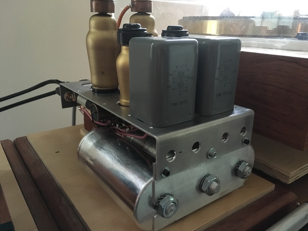
The completed design, still to be built in a final enclosure..
The power supply.
This one is exactly the same as the tube regulated power supply used in my E80F and E182CC design,
of course with the exception of the heater voltages which should read 4Volts and 30Volts to suit this design.
Some words as conclusion.
First: I do hope that this has been an interesting read in implementing some tubes that are seldom seen in an application like this.
Further I gave a look in my kitchen in component preference. In the diagram below I mentioned all of them. This is kind of personal
so I hope this will be appreciated.
The CF50 is a miracle tube.. It is dead silent when tapped on the tube itself during operation at an amplification of over 100 times.
It sounds very much okay (understatement) and I think the looks are something apart. It is a conversation starter for sure.. The
Philips engineers sure were knowing their stuf at that time, a big posthumous chapeau!
Other thing is that I waited a long time before posting this because at first I could not get it right as it was easily overdriven which
which resulted in distorted mids. Overdriven by only a few millivolts, just about 15.. meaning that a 1:30 step-up transformer was not
an option with some cartridges. I fixed that now.
More I was reluctant to share the design as CF50's are already hard to get at reasonable prices, as are AC2's.. just being honest here..
I decided to share it at last because I am so enthusiastic about the performance and did not want to keep this to myself. So maybe you
get inspired or maybe you decide to clone this design.. all is good, it is up to you..
Postscript: Sound..
Before questions drop in about the sound compared to the other designs, remember that this one represents my taste in sound. So, Yes,
I do prefer it over the others. But that is subjective. And I have to point out again that if you use other components, the sound will
become different and does not reflect my taste (which might be better for you). Sound is lifelike, meaning it is compact, energetic,
with realistic tone and body. Voices have a throat and a chest (so hard to get this from a stereo). Lows are voluptuous and do touch
25Hz in my system. Highs are present but not overly, just like in a concert hall. Yes, I do like it!
Below the diagrams (or schematics) for reference. Enjoy!
*Thanks to Bokarev.