Preamplifier grounding
When modding and upgrading a premplifier things can get messy and hum can "suddenly appear"..
I thought it might be worthwile putting up a scheme of how I implement grounding in a preamplifier?
Just to show you what I mean with messy see this picture:
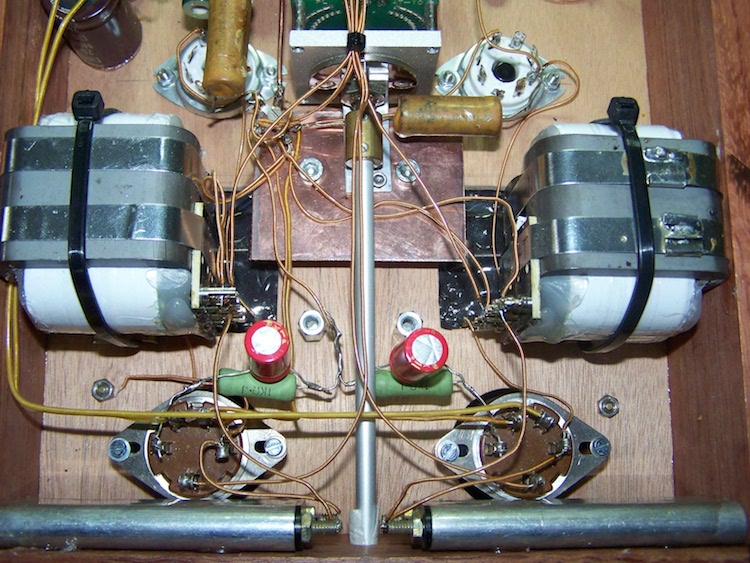
You can see a sort of star-grounding: Lots of wires going to the central point where all the grounding wires are connected to. So the
powersupply grounding as well as both the returns (cathodes) of the used 483 triodes come together at this point. This is classic school
how to to do amplifier grounding. Always safe and supposedly hum-free. Classic school grounding also "dictates" that the input
should be the star grounding and should connect to the chassis which I never do.. Sakuma also uses another grounding scheme which he
calls 2-point earthing method.
Back to the preamplifier.. In this situation it meant hum.. Why? Too many leads going to the star-ground? Something caused an ground-loop.
Hard to determine what the culprit is due to that many leads..
So, I decided to rip it all out and to do it again but now according to my usual grounding method which
makes more sense to me than star-grouding. Why? Let me explain.. I often refer to electronic wiring as if it was plumbing. A plumber does
not use thin pipes at the start to switch to thick pipes later on, that does not make sense. When looking at an electrical circuits some wires
will carry more current than other wires (hence the use of different diameter wires, but that is another topic). Just as the plumber I do not
connect high current wires through low current wires to the central grounding point. I keep supply and return together as much as possible as
well. Each amplifying stage can be seen as a little separate company within an amplifier, with the need to keep supply- and return-paths as
short as possible. This means that I create several star-grounding points, one for each valve with their corresponding power supply
capacitor. Input signal is treated as it were an extension of the interlink with inbetween the attenuator. So both signal and grounding wire
go spearately to the corresponding amplifying stage. If you put the input grounding wire or attenuator grounding contacts to a central star
ground, current has to travel upwards where also current is travelling downwards. See the picture to get what I mean:
This is why I bring these input wires up to the amplifying stage and connect them on that point. Now for the power supply: The biggest current
will flow between the first capacitor and ground, so connect this one directly to the central grounding. All the remaining capacitors can be put in
series to that central grounding point with the exception of the last power supply capacitors just before the amplifying stages. These will be
connected to the star ground of that amplifying stage. This is also the case with the ouput signal: these will also be seen as the start of the
interlink, so grounded at the same star ground of the amplifying stage. As a note I need to add that for safety reasons earthing from power
must be done at the metal chassis. Use a small value resistor and parallelled capacitor to avoid HF-components travelling inwards from the
chassis to the signal ground (a combination of diodes can be added). To avoid earth loops a switch can be placed between the central ground
and the point where it is connected to the chassis (be sure to keep the metal chassis connected to power earth!). This as a note since this
preamplifier has a wooden chassis.
In the picture I tried to visualize the text above. Note that the red wires are not ground and in- and output is drawn for just one channel to
avoid too much lines in the pictures..
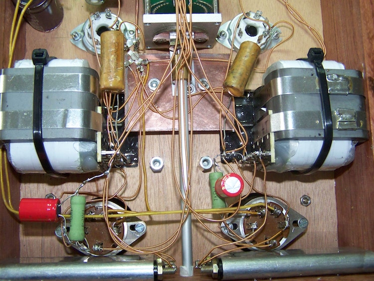
And see picture below when implemented..
I hope this information can be of any help when putting together an amplifier. Also I am convinced that this grounding method has a positive
influence on sound quality (really!)..